GENESIS: Documentation
Related Documentation:
RTXI injector Module Validation
A step by step validation procedure for the RTXI it injector module. This
procedure should be run prior to connecting RTXI to an external amplifier. It
enables the correct application of scaling factors to match RTXI output and input
to the units employed in a source file containing a stimulus signal. The following
steps should be initiated from the desktop of your machine that has RTXI
installed.
Validation Procedure
Activate the stimulus signal
- Start a terminal window.
- At the terminal window prompt enter rtxi.
- From the RTXI Control drop-down menu select Plugin Loader.
- From the Open File dialog box select injector.so.
- In the new Open File dialog box go to /home/Suterlab.
- Select the folder Desktop/dynamic–clamp/stim-src.
- Select and open the validation input file Offset400.txt.
- In the Injector control window popup
- Set Gain GABA to 1e9.
- Set Global Offset to 0.
- Set GABA Enabled? to 1.
- Click the Modify button at the bottom of the panel. This will
cause the altered values to change color from red to black.
- Click the Pause button.
The square pulse waveform read from the input file (Offset400.txt) is now being
generated internally within RTXI by the injector.so plugin.
Visualize the internally generated signal
- From the RTXI Control drop-down menu select Oscilloscope. (The
oscilloscope window should appear.)
- Right click on the Oscilloscope window, select Properties.
- In the Oscilloscope Properties dialog box set the Channel drop-down boxes to the
values:
- Click the Active button at right hand end of the Channel boxes.
- Set the Display Properties Scale to 200 mV/div.
- Click the Apply button at the bottom left of the Oscilloscope Properties
dialog box.
You should now see the generated square-pulse with an amplitude of 2 divisions on
the RTXI oscilloscope screen. The amplitude is equivalent to 400 mV (see the
scale in the bottom left of the oscilloscope window). Each pulse is 1 ms in duration
to give 5 pulses per 5 ms division (Scale on bottom right hand side of the
oscilloscope window gives the absolute temporal duration of the oscilloscope
window).
Connect internally generated RTXI signal to the DAQ output
- From the RTXI Control drop-down menu select Connector.
- In the Connector Panel dialog box set the Output Block to
Injector2 and the Channel to GoutGABA.
- In the Connector Panel dialog box set the Input Block to the DAQ
board name (here NI PCIe–6251 14), and the Channel to Analog
Output 0.
- Click the right facing arrow “==>” to connect the RTXI output block
to the DAQ board input block.
Enable the analog output of the DAQ
- From the RTXI Control drop-down menu select System Control and
check the Device is the DAQ board (here NI PCIe–6251).
- In the System Control panel set the Analog Channel to Output
channel number 0.
- Click the Active button on the right hand side.
- Click the Apply button at the bottom left hand side of the panel.
- Configure the hardware oscilloscope to 5 ms and 200 mV.
Configure RTXI software oscilloscope to monitor incoming signal
- From the RTXI Control drop-down menu select Oscilloscope.
- Right click on the oscilloscope window and select the oscilloscope
Properties.
- Select:
| NI PCIe–6251 14 | Output | Analog Input 0 |
- Click to select Active at right hand end.
- Set Display Property Scale to 200 mV/div.
- Select Line Property Color “blue”.
- Click Apply button on lower left hand side of the oscilloscope panel.
Enable the input signal from the DAQ
- From the RTXI Control drop-down menu select System Control
- Select Device NI PCIe–6251.
- Select: Analog Input Channel Input 0.
- Click Active button at right hand end.
- Click Apply button at bottom left hand side of panel.
- The RTXI input signal (identical to the output signal for this
validation test) should now appear on the screen of the RTXI software
oscilloscope.
- We measure ≈ 0.1 ms between the input and output traces of the signal.
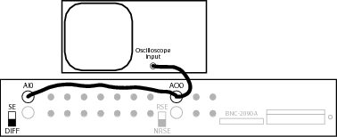
Hardware Cabling and Switches